To build your NISSE keyboard, you'll need the following:
Esrille New Keyboard Kit
Cherry MX switches without fixation pins (76 switches in total)
USB 2.0 Type A to B cable (not included in the kit)
The PIC18F4550 microcontroller included in the kit is preprogrammed with the USB bootloader and the NISSE keyboard firmware.
In the following sections, components marked with direction marks have polarity. Be sure to insert them in the same directions as the silkscreen on the PCBs.
The keyboard controller board
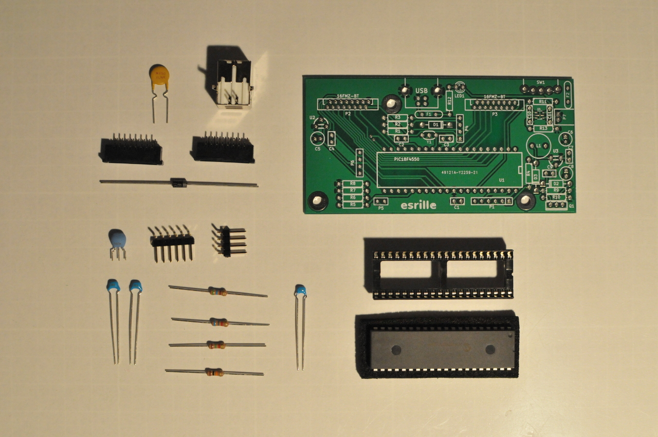
Solder the following components onto the keyboard controller PCB as shown in Figure 2.
Label
Component
Remarks
C1
0.1uF ceramic capacitor
104
C2
0.22uF ceramic capacitor
224
C3
0.1uF ceramic capacitor
104
D1
1N5817 diode
direction
F1
RXEF050 polyswitch
P1
6-pin right-angle header
used only with the PICkit 3 in-circuit debugger
P2
16FMZ-BT FFC connector
direction
P3
16FMZ-BT FFC connector
direction
P4
4-pin right-angle header
PIC18F4550
40-pin DIP socket
direction
R1
560Ω resistor
R2
6.8kΩ resistor
R3
1.5kΩ resistor
R4
10kΩ resistor
USB
USB B plug
Y1
16MHz ceramic resonator
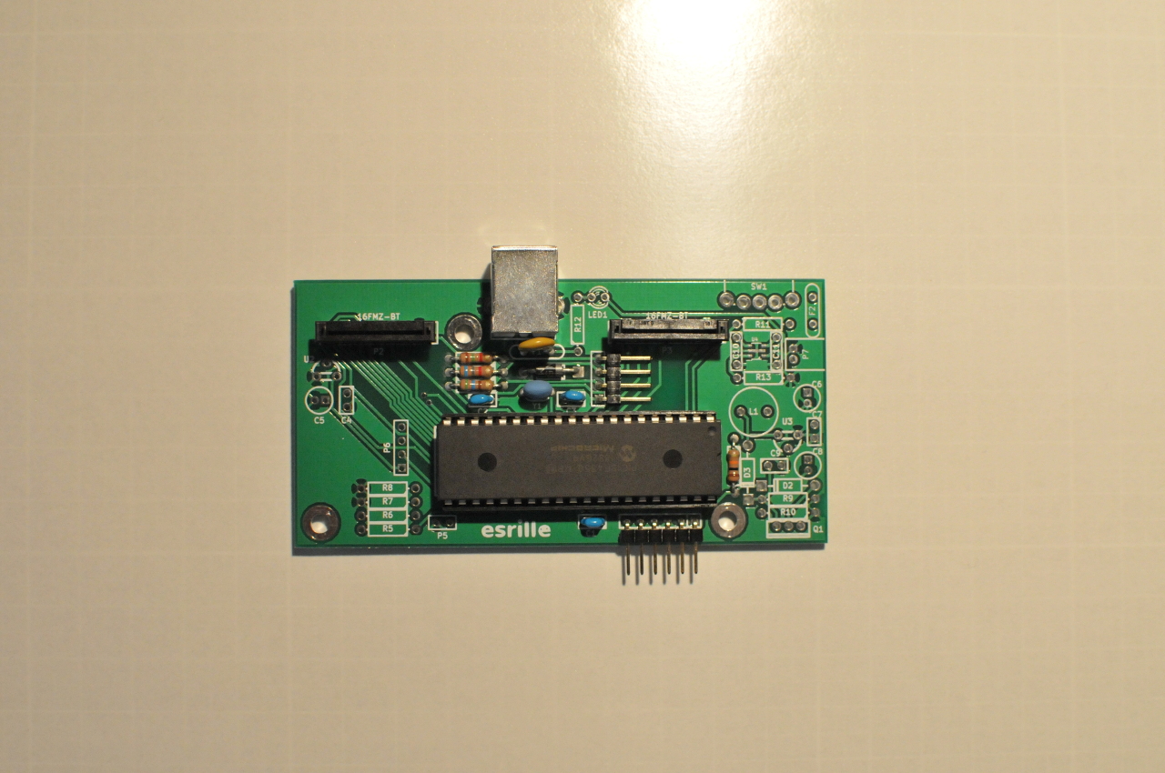
Note: Only the components listed in the above table need to be soldered.
Insert the PIC18F4550 microcontroller into the 40-pin DIP socket after every component is soldered.
The first pin should be at the top-right position as shown in Figure 2.
The Right Hand Side Board
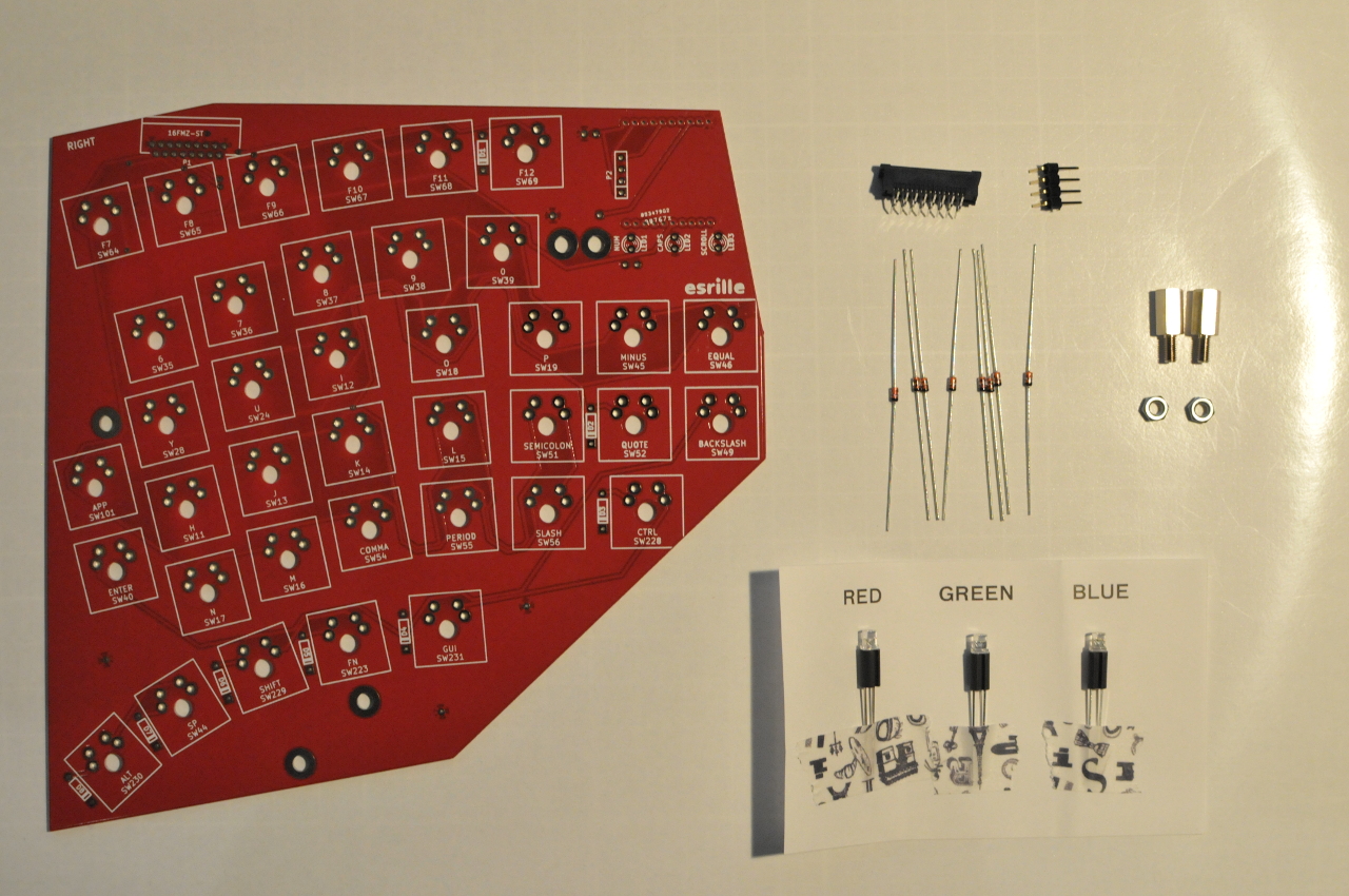
Solder the following components onto the right hand side PCB.
Label
Component
Remarks
LED1
Red LED with 8mm LED spacer
direction Num lock
LED2
Green LED with 8mm LED spacer
direction Caps lock
LED3
Blue LED with 8mm LED spacer
direction Scroll lock
P1
16FMZ-ST FFC connector
direction
P2
4-pin right-angle header
SW11 〜 SW231 (38 in total)
Cherry MX switch
D1 〜 D8 (8 in total)
1N4148 diode
direction
Note: The right hand side PCB and the left hand side PCB are exactly same. To build the right hand side board, make sure the silkscreen "RIGHT" is at the top-left corner as shown in Figure 3.
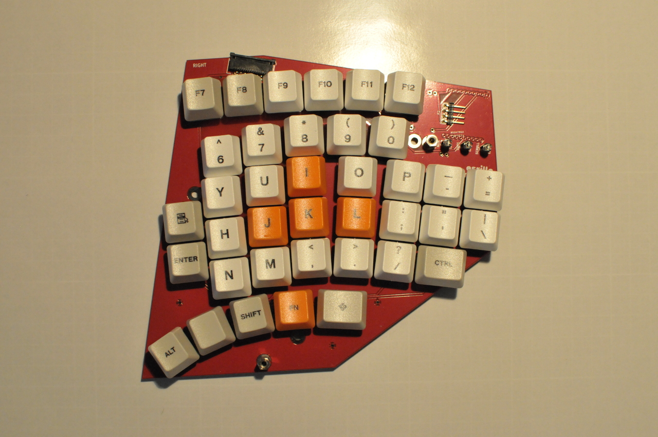
After every component is soldered, fit the keycaps onto MX switches,
and then tighten two 10mm high threaded hex spacers with hex nuts through the 3M holes at the bottom and right as shown in Figure 4.
Tips for soldering MX switches
It is not very easy to solder MX switches well aligned in a row without using a jig.
A jig can be plastic rail that is drilled at 18.8mm intervals like shown in Figure 5.
Note: Jigs are not included in the Esrille New Keyboard Kit.
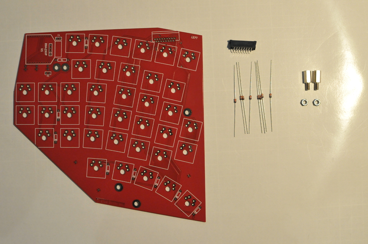
The Left Hand Side Board
Solder the following components onto the left hand side PCB.
Label
Component
Remarks
Non-labeled 17-pin silkscreen at top-right
16FMZ-ST FFC connector
direction
Non-labeled square silkscreen (38 in total)
Cherry MX switch
Non-labeled diode silkscreen (8 in total)
1N4148 diode
direction
Note: No component is required at C1, R1, P3, and U1 around the top-left corner.
Note: The left hand side PCB and the right hand side PCB are exactly same. To build the left hand side board, make sure the silkscreen "LEFT" is at the top-right corner as shown in Figure 6.
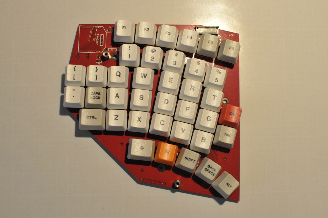
After every component is soldered, fit the keycaps onto MX switches,
and then tighten two 10mm high threaded hex spacers with hex nuts through the 3M holes at the bottom and left as shown in Figure 7.
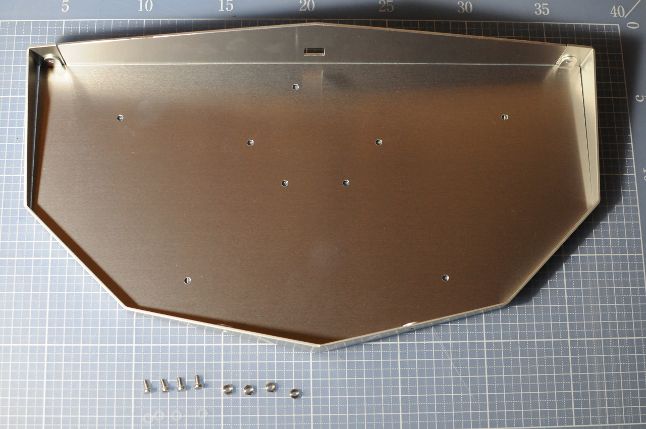
The Aluminum Chassis
The aluminum enclosure of NISSE is composed by three parts:
Part A: Lid (anodized red),
Part B: Chassis (non-anodized), and,
Part C: Chassis (anodized white).
Joint the part B and part C using two angled stays and two straight stays:
Tighten six stainless slotted-head screws over six nylon washers from the sides with hex nuts.
Tighten two M3x6mm low head screws from the bottom with hex nuts.
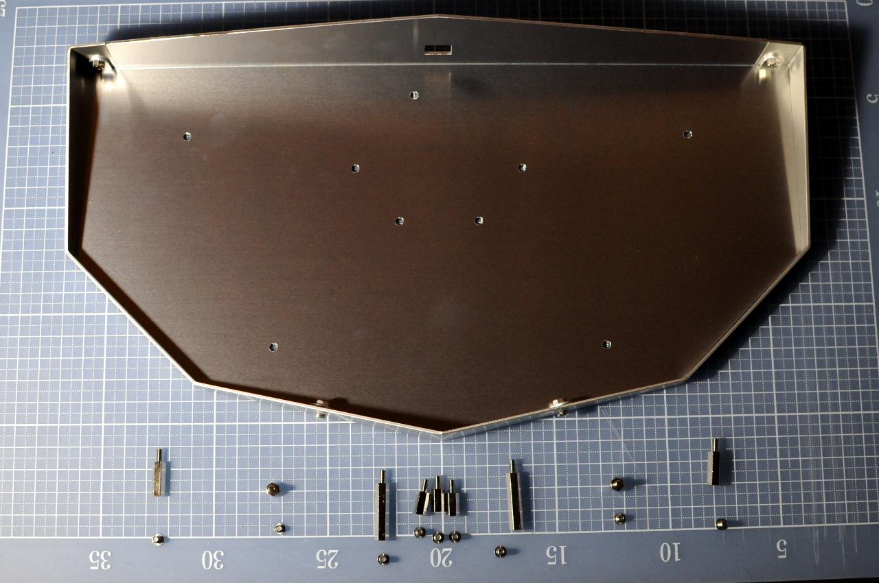
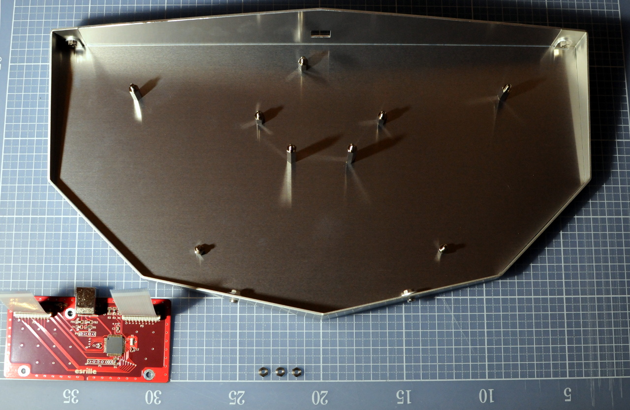
Joint nine hex spacers for holding PCBs.
From left to right, the heights of spacers are 15mm, 5mm, 10mm, 25mm, 10mm, 25mm, 10mm, 5mm, and 10mm.
Use M3-4mm low head screws to joint 5mm high hex spacers, and M3-6mm low head screws to joint other hex spacers.
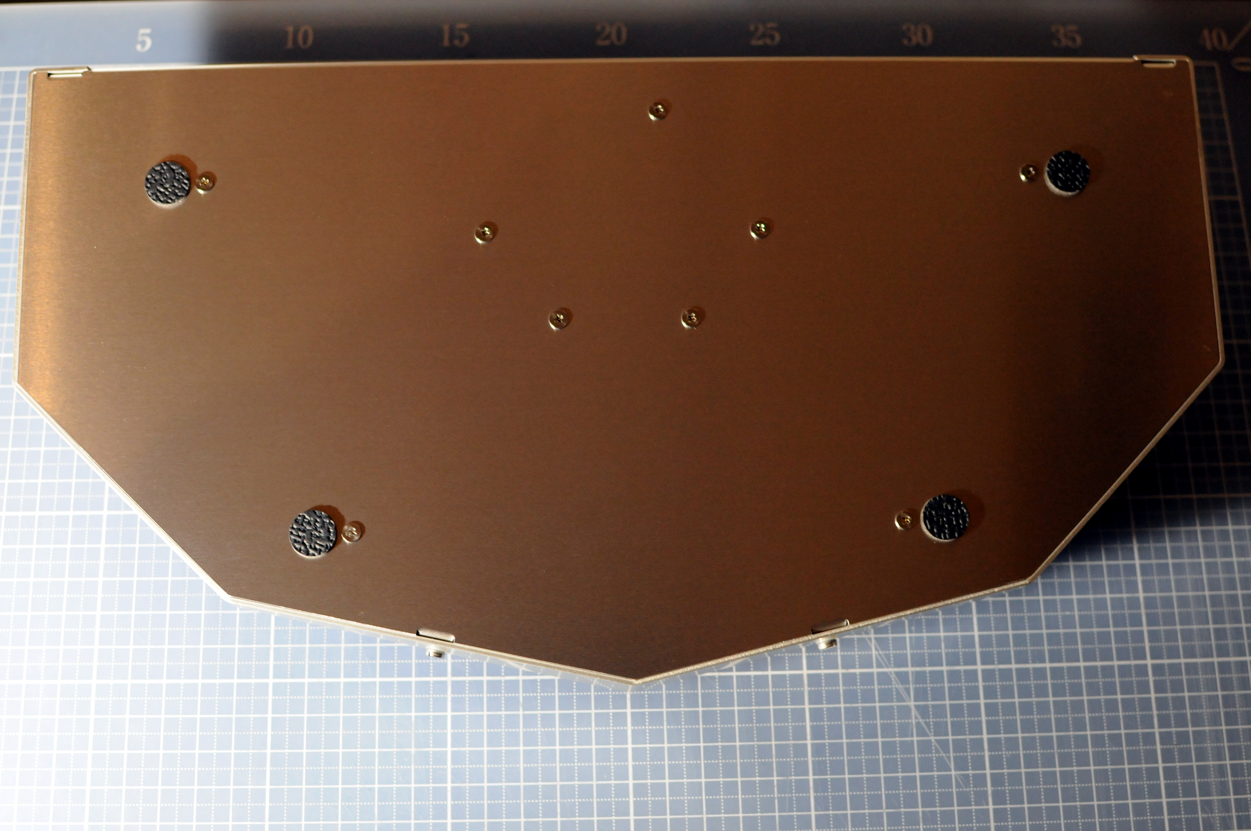
Stick four polyurethane round feet to the bottom of the chassis.
Circuit boards installation
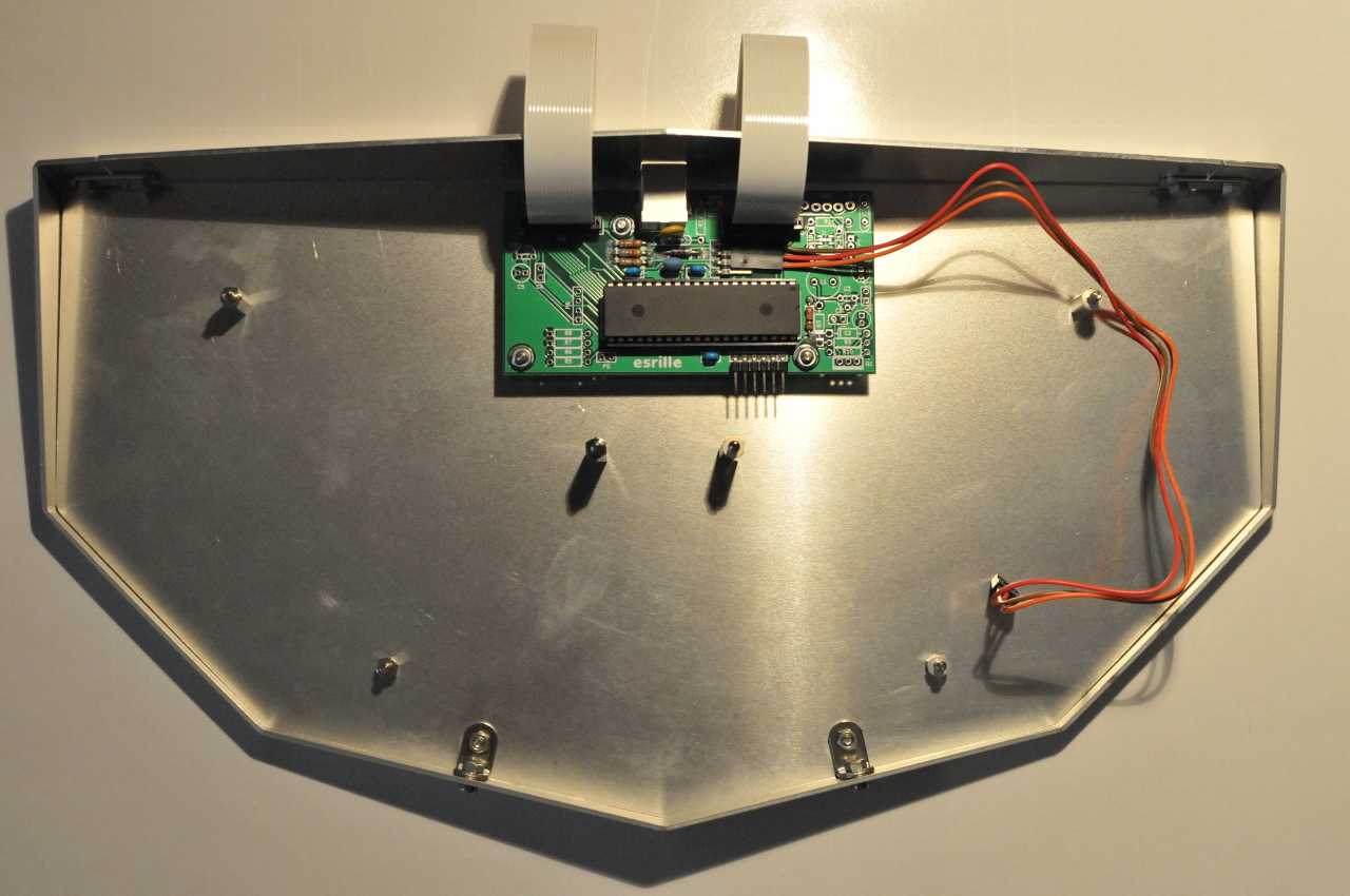
Connect the QI cable and two FFC cables to the controller board, and joint it to the chassis with hex nuts.
Note: If your kit comes with three pin QI cable, leave the bottom header pin open as in Figure 14.
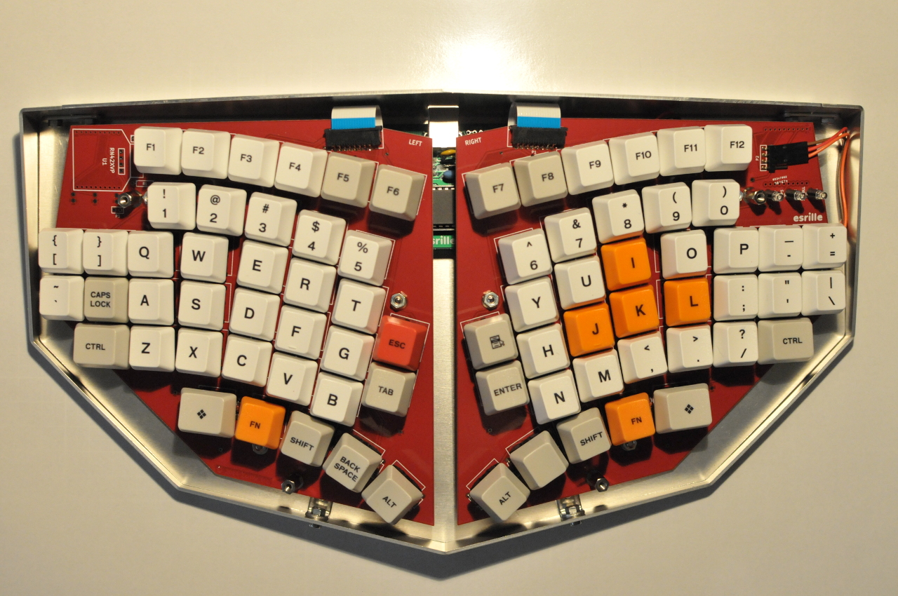
Joint the left hand board and right hand board to the chassis with hex nuts.
Use two nylon washers at each hex spacer to sandwich the board.
Finally, cover the chassis with the lid and make sure three LED heads are out of the lid holes.
Screw down the lid to the chassis with four brass slotted-head screws over four nylon washers to protect the color anodized surface of the lid.
Congratulations and enjoy your NISSE keyboard!
Note: To update the firmware, connect the NISSE keyboard to the host PC holding the ESC key.
The red LED will start blinking to indicate that the keyboard is in the bootloader mode.
Use HIDBootloader included in the Microchip Libraries for Applications provided by Microchip to update the firmware.